Monday, August 26, 2024
Aug 26 (Mon) - Room Electric - Pt. 1
This is the first article in a series.
 The project: upgrading the electric in this room. I already did some of the work, it’s past time to continue. My philosophy going forward is simply this: “Progress, Not Perfection”.
.
I simplified my electric plan. I’m adding lights and outlets. Lighting will be low and high intensity. Low for when I’m at the workstation, low and high when I’m at the work bench. Each will be controlled by a separate light switch. I’ve been using that lighting setup for quite some time and it works very well. But it’s all extension cords and that needs to stop. Light switches come first.
.
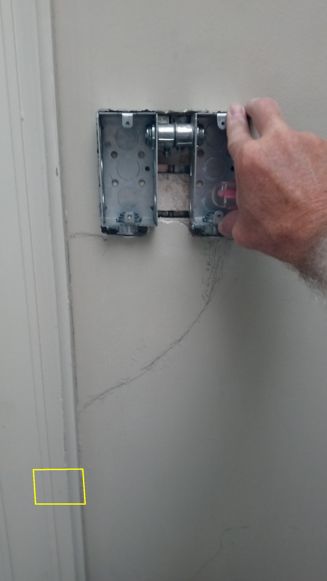
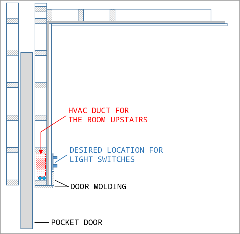 Putting the switches where I want is complicated by what’s inside the wall. As shown in this picture, there’s a duct inside the wall right where I’d normally put deep boxes.
.
I decided to use shallow boxes. I’ll attach them to the lathe. They’ll stand proud of the adjacent plaster by about an inch. Wiring will exit the bottom of the boxes and travel down the wall and over to the molding. Behind the molding the wiring will transition into the dead space next to the duct (two blue circles). I’ll cover the conduit with wood where it travels along the lathe. I expect to cut just one piece of lathe and not disturb the molding.
.
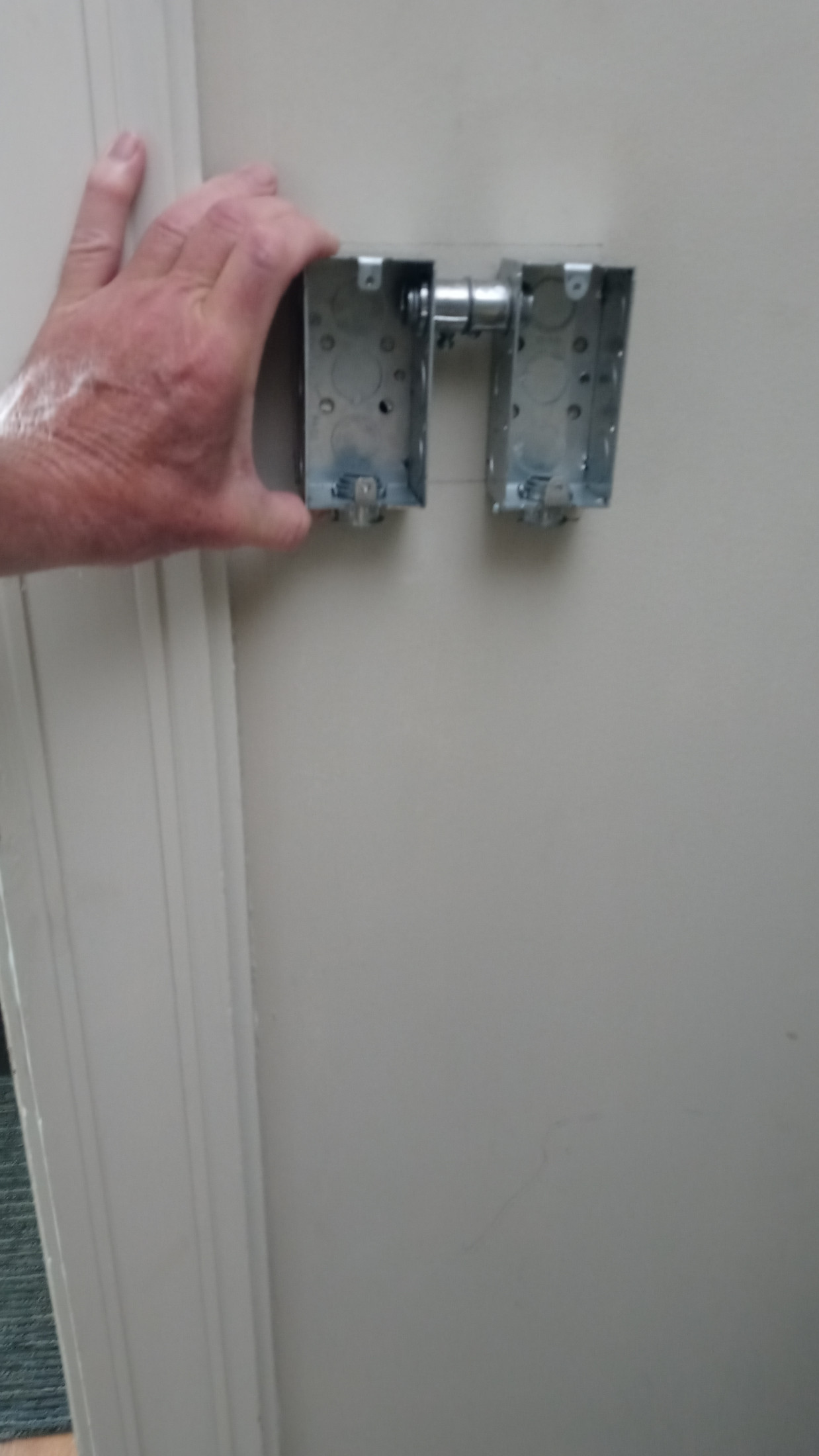 I assembled the boxes, held them against the wall at the ideal height above the floor, leveled ‘em, and penciled the location.
.
You may ask: Why am I using two switch boxes? Why not use just one large one? Reasons: Large boxes aren’t available in shallow depth, and shallow boxes can’t be ganged together. That small piece of conduit between the boxes isn’t necessary from a wiring perspective but it holds the boxes together which greatly simplifies marking and cutting.
.
.
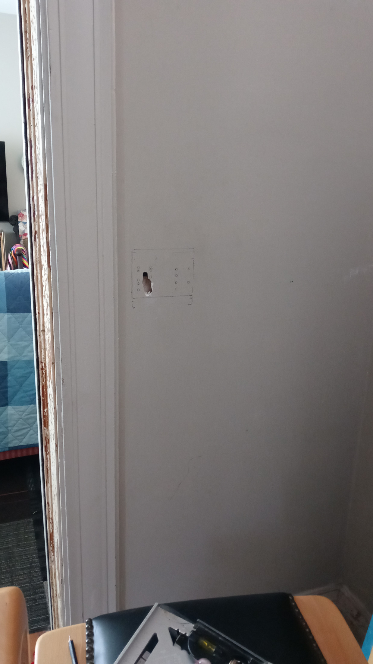 I chipped a small amount of plaster from the wall to find the gap between the lathe.
.
.
.
.
.
.
.
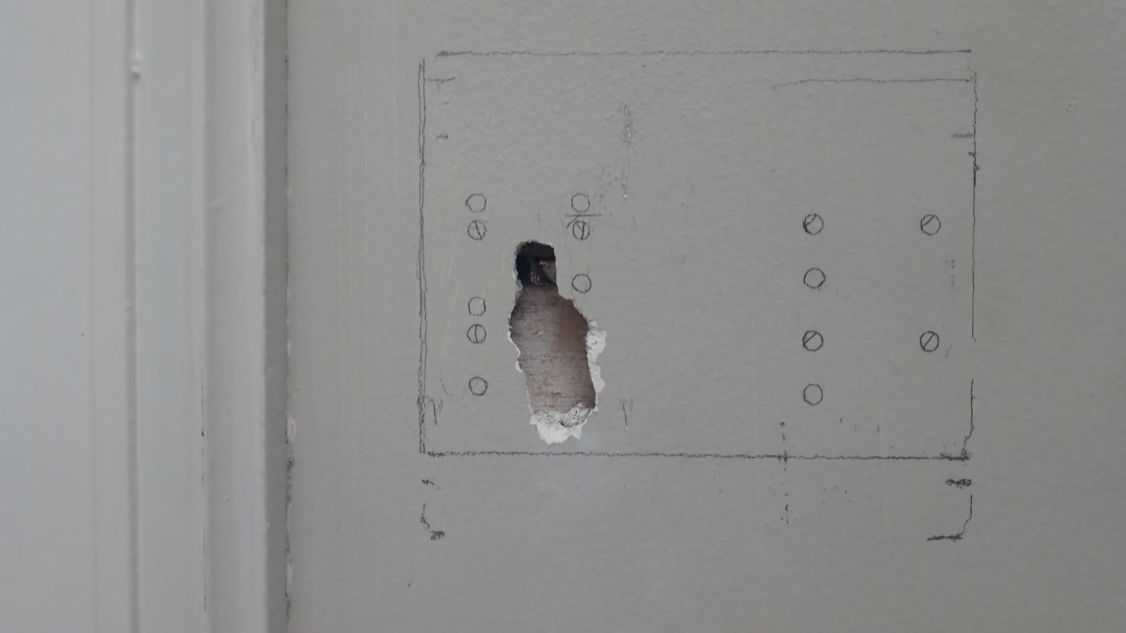 I then slid the box up and down a bit from the ideal location until all eight mount holes for the boxes were located on lathe and not on a gap between.
.
I’ll use eight screws to mount those boxes to the lathe. If I carefully remove the plaster and leave the lathe undisturbed, the lathe should provide an adequate surface on which to mount the boxes. My pencils may look messy but I understand it. The boxes ended up about an inch higher up the wall from ideal height above the floor.
.
 With the plaster removed and the boxes held against the lathe I penciled where the flexible metal conduit (FMC) will go. FMC will drop from each box then curve over to the door molding. The yellow box I added indicates where the FMC will transition from ‘on top of the lath’ to ‘in the dead space next to the duct’.
.
.
.
.
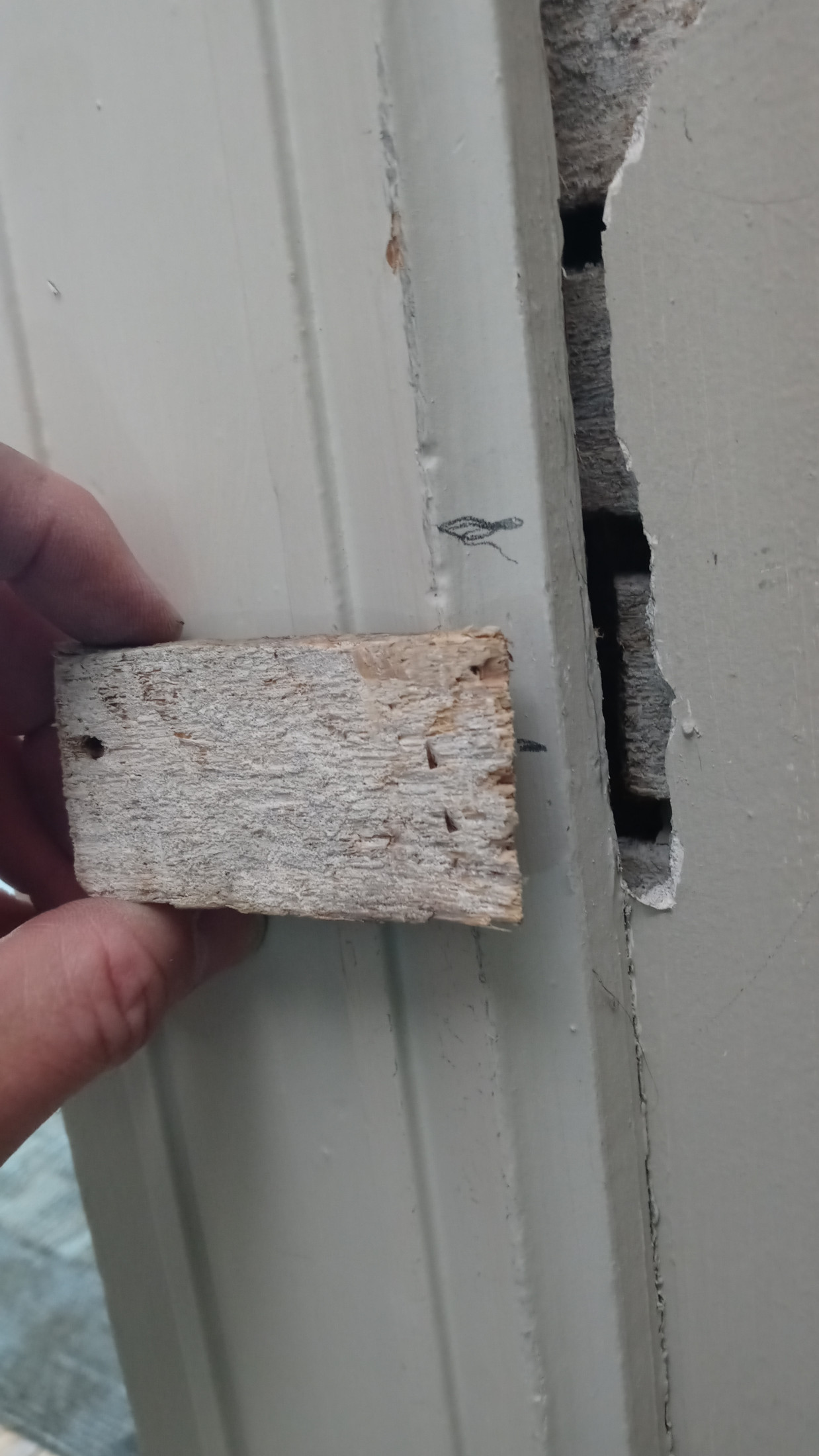 I located the piece of lathe I needed to remove from behind the molding. As seen here, that piece was roughly three inches long. It came out without a hitch and the rest of that piece of lathe remains undisturbed. Helpful tips when doing this: Use a sharp saw blade. I used a new sawzall blade. Orient the blade such that you must pull the blade toward you in order to cut the lathe. With slight downward pressure, pull slowly toward you.
.
.
.
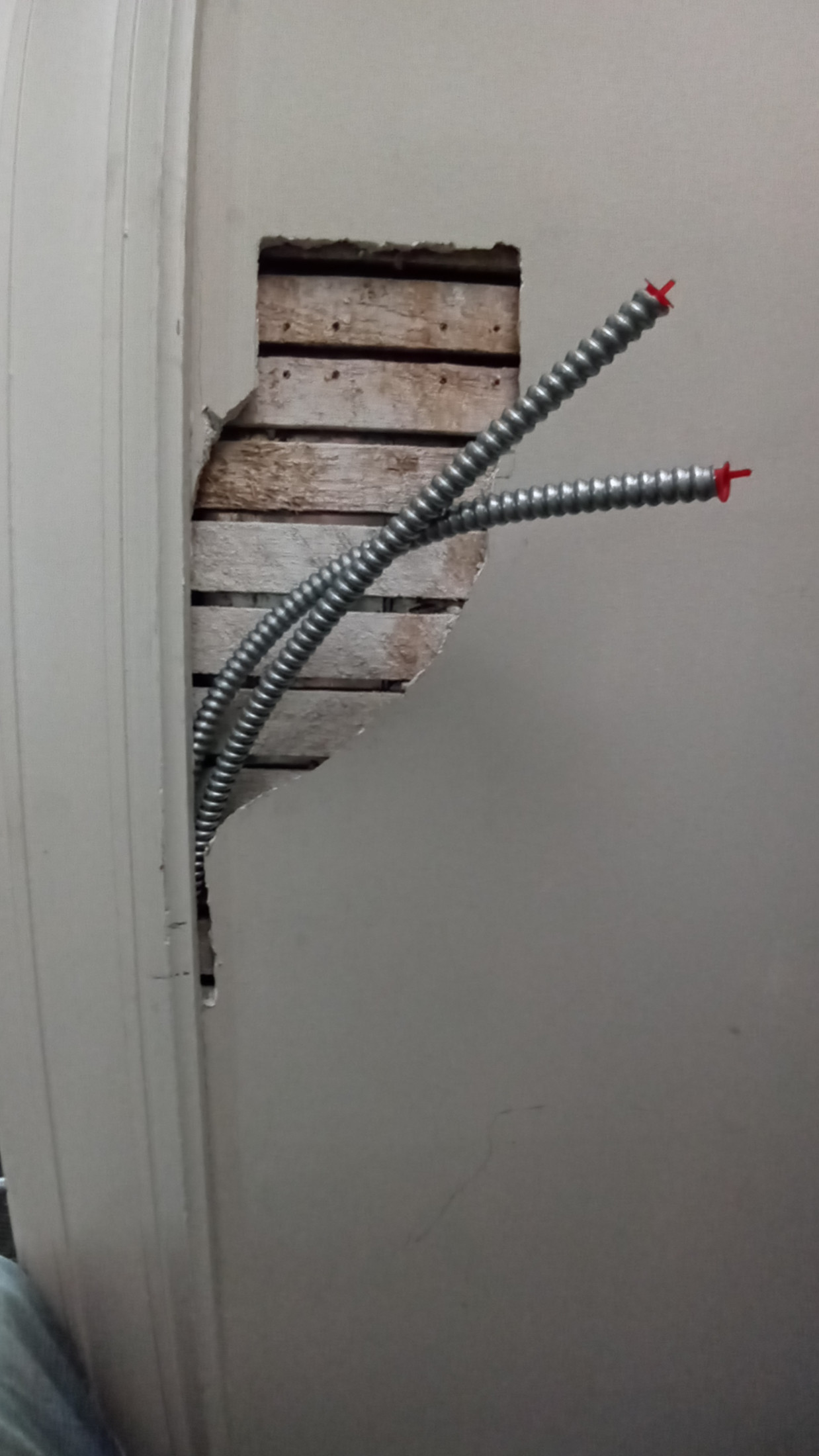
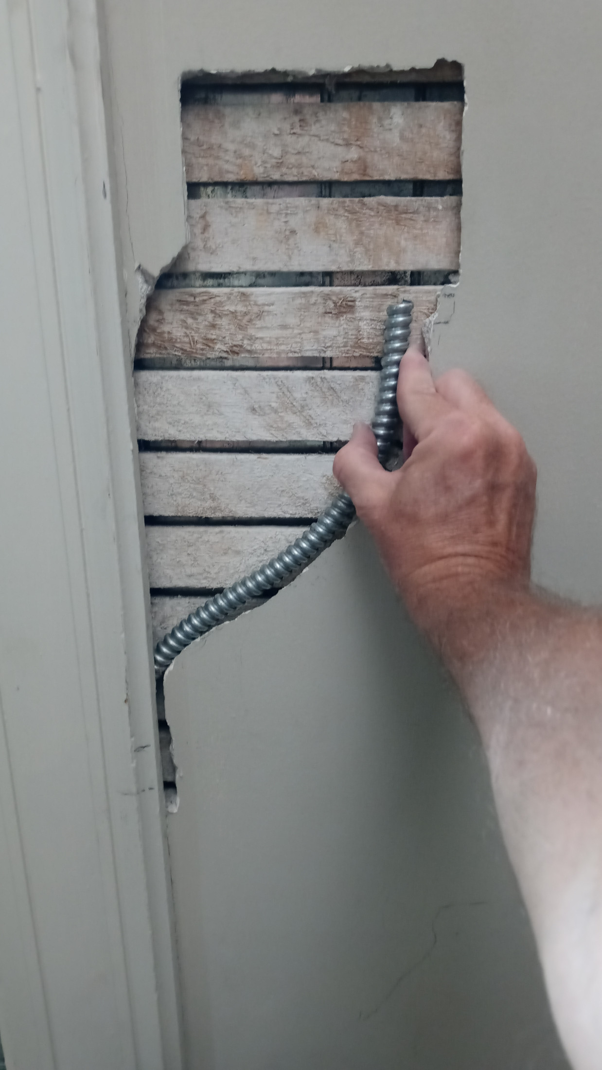 Here’s a test fit of FMC from inside the pocket up to where the boxes will be. It easily passed through the hole I made by removing that small piece of lathe. Nice. That FMC is steel, not aluminum. Steel is all I use. It’ll be covered with an inch of wood.
.
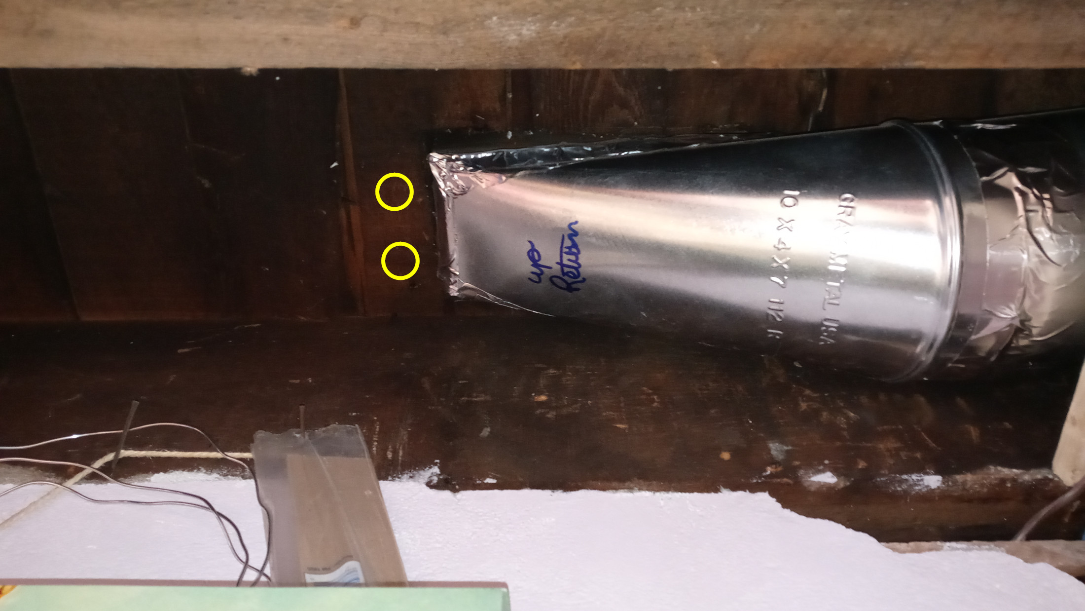 I drilled two holes through the floor next to the duct for the FMC.
.
.
.
 Here’s both FMCs from the basement, up through the dead space next to the duct, and into the room. They’re ready to be attached to the boxes. To be continued…