Sunday, September 1, 2024
Sep 1 (Sun) - Room Electric - Pt. 4
The electrical schematic.
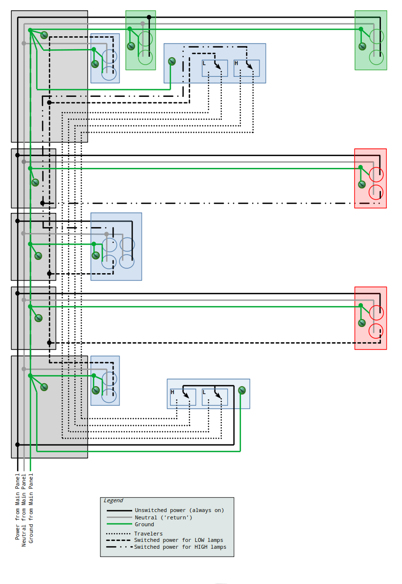 This article is about the electrical schematic. I used non-standard electrical symbols in order to speed up the creation process. The diagram will serve its purpose as is. A one-page PDF of the schematic is here.
.
To maintain continuity between the schematic and the floor plan I used the same colors in each: green exists today, blue is what I’m currently installing, red is for the future if need be.
.
The five charcoal-shaded boxes down the left side of the print are junction boxes. A few points about those:
.
1. I may be able to combine some of these depending on where the floor joists are in relation to the floor plan.
.
2. The National Electric Code limits how much stuff can be stuffed inside each box. I was concerned that the two large boxes that ‘bookend’ the wiring run might be ‘too busy’ (i.e. have too many wires). If I use the largest boxes I can buy at the local box stores I’ll have plenty of room.
.
You may notice that the large blue box in the center of the schematic contains two duplex receptacles. The outlets on the right receptacle will always be powered, they’re for the workbench and 3D printers. I’ll split the left receptacle: the top outlet is for the high light, the bottom outlet is for a low low light if needed.
.
The next step is to go down to the basement and study the floor joists under the room. I’ll figure out where each junction box will go. Stay tuned.
Add comment
Fill out the form below to add your own comments